
Skip to content

Mechanical product design · 3D CAD engineering From Concept to Manufacturing-Ready Product.

DimenShift delivers precision-driven mechanical product design and 3D CAD engineering that transforms ideas into accurate, functional, production-ready solutions.

01Services

Engineering services, from first sketch to release.

Each service can stand alone or connect into a complete development program. Open a service to see what it involves and what you receive.

Turn a requirement into a mechanism: part layout, motion, load paths and assembly strategy are defined before detailed CAD, so the design is built on decisions rather than guesses.

Deliverables

  • Concept layouts and design options
  • Mechanism and part architecture
  • Material and process direction
  • Design review notes

Typical use case

You have a validated need or a rough sketch and need an engineered product architecture.

01 · Mechanical Product DesignConcept sketches, a working mechanism and its CAD architecture

Part and assembly models built with controlled relationships, so a change to a key dimension updates the design cleanly instead of breaking it.

Deliverables

  • Parametric part models
  • Structured assemblies
  • Neutral exports (STEP, IGES, STL)
  • Rendered review views

Typical use case

You have drawings, sketches or a prototype and need a clean, editable 3D model.

02 · 3D CAD ModelingDriving a parametric assembly from its feature tree

Part and assembly drawings that define dimensions, tolerances, materials and notes, so manufacturing partners can quote accurately and produce consistently.

Deliverables

  • Part and assembly drawings
  • Dimensions, tolerances and notes
  • Section and detail views
  • Bill of materials

Typical use case

Your design exists in CAD but cannot go to suppliers without complete documentation.

03 · Engineering DrawingsHousing drawing with sections, GD&T and title block

Review and refine geometry for the intended manufacturing route — wall thickness, draft, radii, tool access and part count — before tooling or machining costs are committed.

Deliverables

  • Manufacturability review
  • Geometry corrections
  • Part consolidation options
  • Revised CAD and drawings

Typical use case

Your prototype works, but quotes are high or suppliers keep flagging problems.

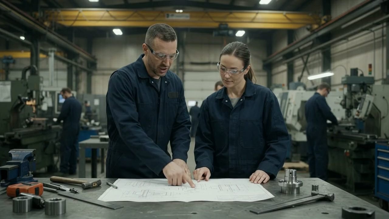
04 · Design for Manufacturing (DFM)Design checked against the machining route on the shop floor

A staged development process with defined reviews and deliverables at each gate, carrying a product from first concept through to a manufacturing-ready design package.

Deliverables

  • Staged development plan
  • Iterative CAD revisions
  • Prototype-ready files
  • Release documentation package

Typical use case

You are a startup or product team that needs one engineering partner for the whole journey.

05 · Product DevelopmentConcept to release through reviewed development gates

Rebuild paper drawings, 2D files, legacy formats or supplied measurement data as accurate, editable 3D models with updated documentation.

Deliverables

  • 2D-to-3D conversion
  • Legacy file rebuild
  • Models from supplied measurements or scan data
  • Updated drawings

Typical use case

A part is still in use but has no usable CAD — only a drawing, an old file or the part itself.

06 · CAD Conversion & Reverse EngineeringLegacy drawing and worn part rebuilt as editable CAD

Refine an existing design to reduce mass, part count, assembly effort or production cost while protecting the functions and interfaces that matter.

Deliverables

  • Opportunity review
  • Geometry and assembly refinements
  • Before / after comparison
  • Updated CAD package

Typical use case

Your product is in use, and the next revision needs to be lighter, simpler or cheaper to build.

07 · Design OptimizationOriginal and optimized bracket compared side by side
  • 01

    Concept → production

    One workflow from first idea to release package.

  • 02

    Built to be made

    Manufacturing constraints designed in, not patched in.

  • 03

    Documented intent

    Models and drawings that explain themselves.

  • 04

    Clear deliverables

    Defined outputs at every stage of the work.

Assembly sequence

From individual components to a complete assembly.

01 · Assembled

One manufacturing-ready product.

Concept design to CAD conversion
7services
Structured concept-to-release process
8stages
Legacy drawings rebuilt as editable CAD
2D → 3D
STEP · IGES · DWG · DXF · STL · PDF
6formats
Tolerance compliance
± 0.005mm
Certified quality management
ISO 9001
Fast-track DFM turnaround
48h
Production-ready CAD / CAM
100%
02Process

An engineering workflow you can watch.

Eight stages take a product from requirement to release package. Scroll through them and follow one gear reducer from its first design envelope to a released product.

  1. 01Understand

    Define the problem before drawing the part.

    Requirements, operating conditions, constraints, target cost and production volume are captured first. What the product must do sets the design envelope.

    • Requirements brief
    • Design envelope
    • Constraints list

    Stage image: A monitor showing the gear reducer’s design envelope in CAD, a translucent box of 320 by 210 by 180 millimetres around the concept, above a printed requirement sheet listing input torque, power and ratio.

  2. 02Concept

    Explore form and architecture.

    Quick forms and layouts test how the product could work, where the major parts sit and how it will go together — fast, before detail slows iteration down.

    • Concept options
    • Layout sketches
    • Direction review

    Stage image: Three hand-sketched concept options for the gearbox laid out on a workbench, inline, parallel and coaxial, with the parallel layout marked as preferred and two of the layouts modelled on the monitors behind.

  3. 03Engineer

    Build intent into the geometry.

    The chosen concept becomes parametric CAD. Construction geometry, key dimensions and relationships are defined so the design responds predictably to change.

    • Parametric model
    • Key dimensions
    • Design intent

    Stage image: The chosen gear reducer as a parametric CAD model on screen, its gears and shafts shown in wireframe inside the housing with driving dimensions and the feature tree beside it.

  4. 04Develop

    Detail every component, then assemble.

    Housing, shafts, gears, bearings, seals and fasteners are each modeled to be made, then structured into an assembly that reflects how the product is built.

    • Detailed parts
    • Assembly structure
    • Standard components

    Stage image: Two monitors showing the gear reducer’s assembly and its exploded view with every part, while the machined housing, gears, shafts and bearings lie on the desk in front.

  5. 05Validate

    Check the fit before the first cut.

    Section views, clearance checks and interference detection in the CAD assembly catch fit problems while they cost minutes to fix — not tooling.

    • Section reviews
    • Clearance checks
    • Interference checks

    Stage image: A section view through the gear reducer in CAD with red markers on the gear mesh and bearing seats where clearances and interferences are being checked.

  6. 06Document

    Communicate it without ambiguity.

    Drawings define dimensions, tolerances, materials and notes, so manufacturing partners can quote accurately and make parts consistently.

    • Part drawings
    • Assembly drawing
    • Bill of materials

    Stage image: The gear reducer’s drawing sheet on screen, with dimensioned views, section A–A and a title block, and the printed drawing set and a caliper on the desk.

  7. 07Manufacture

    Prepare for the real process.

    Models and drawings are prepared for the intended manufacturing route, with manufacturability feedback resolved before anything is released.

    • Manufacturing files
    • DFM revisions
    • Supplier handoff

    Stage image: CAM toolpaths for the gearbox housing on a monitor while a CNC machining centre cuts it in the shop behind, with the machined aluminium housing and its drawing on the bench.

  8. 08Deliver

    Release a complete product package.

    You receive a manufacturing-ready design package: editable CAD, neutral formats, drawings, bill of materials and a clear revision record.

    • Release package
    • Neutral CAD formats
    • Revision record

    Stage image: The finished gear reducer on a workbench beside a laptop showing the stage 8 design release package with its CAD, drawing and documentation files.

033D showcase

Inspect the assembly.

Every component of this worm-gear reducer is modeled individually. Switch views, turn the model, and select parts in the bill of materials to see where each one sits.

The reducer as it leaves the bench: cast housing closed, both shafts turning under power.

Swipe in any direction to rotate
Reduction
32:1
single-start worm, 32-tooth wheel
Centre distance
65 mm
worm axis to wheel axis
Envelope
260 × 240 × 260 mm
over feet and flanges
Output shaft
Ø24 mm
keyed, at right angles to the input
04Problem → Solution

Where product development breaks — and how engineering prevents it.

  1. 01

    Problem

    The prototype works, but it cannot be manufactured economically.

    Engineering response

    Design for manufacturing runs through development, so cost and process constraints shape the part before quotes come back.

  2. 02

    Problem

    Parts arrive and do not fit together.

    Engineering response

    Clearances, tolerances and interferences are checked in the CAD assembly before a single part is ordered.

  3. 03

    Problem

    Suppliers cannot quote from the files you have.

    Engineering response

    Complete drawings, bills of materials and neutral CAD formats give suppliers what they need to quote and build.

  4. 04

    Problem

    Every design change breaks the model.

    Engineering response

    Parametric models with documented design intent make revisions predictable instead of a rebuild.

05About · Approach

An engineering partner for products that have to be built.

We work with founders, startups, manufacturers and product teams who need engineering that holds up in production — not just a convincing render.

  • Mechanism first

    Form follows function. Every surface has a reason to exist and a way to be made.

  • Manufacturing in view from day one

    Process, tooling and assembly are considered while the design is still cheap to change.

  • Traceable design intent

    Key dimensions and relationships are controlled, so the model survives the next revision.

  • Decisions in plain language

    Technical trade-offs are explained clearly, so founders and product owners can decide with confidence.

06Capabilities

Capabilities and deliverables.

What the work covers, what you receive, and the file formats we exchange with your team and suppliers.

Engineering disciplines

  • Mechanical product design
  • Parametric 3D CAD
  • Assembly modeling
  • Technical documentation
  • Design for manufacturing
  • Design optimization

Deliverables

  • Part and assembly models
  • 2D engineering drawings
  • Bills of materials
  • Exploded and section views
  • Rendered review visuals
  • Release documentation packages

File formats exchanged

  • STEP / STP
  • IGES / IGS
  • DWG
  • DXF
  • STL
  • PDF
07Selected work

Selected work and studies.

Illustrative studies show how typical engineering problems are approached. Client projects are added here as they can be shared.

Start a project

Have a product that needs to be built?

Send whatever you have today. We review it, ask the questions that matter, and outline the engineering needed to take it to manufacturing.

Nothing drawn yet? A sketch or a photo is enough to start.

What happens next

  1. 1

    Review

    Your description and files are read against the engineering work involved.

  2. 2

    Clarify

    Questions come back to confirm requirements, constraints and priorities.

  3. 3

    Propose

    You receive a recommended scope with deliverables and a quote.

What you can send

4 groups
Drawings
PDFDWGDXF
Models
STEPIGESSTL
Photos & sketches
PNGJPGWEBP
Archives
ZIP

Rough information is fine — the first step is understanding the problem.